Basis
Transforms
SceneGraphNode
A SceneGraphNode Node is the basic Node used to build a Scene Value by gathering the Scenes from its children SceneGraphNode Nodes. The Node structure also allows to manage how the Nodes’ transforms are related to each other through the parent_matrix and ìnherits_transform plugs of the SceneGraphNode Nodes.
Animation Controller
A Controller Node is an animation-process specific SceneGraphNode whose purpose is to provide a visual artefact for the animators to select and interact with (changing transform channels and parameter channels).
Controller Nodes are linked to the character’s Asset Node so that the rig is always evaluated locally w.r.t. the Asset space, allowing global translation, rotate and scale of the character and its rig directly from the Asset. Hence, when building the rig for a character, prefer using the rig_world transform plug when not depending on the Asset space.
Joint
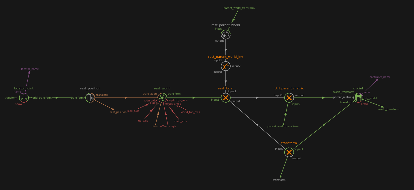
Create a joint by importing a JointModule-dev in the Node Editor. Its main components are a locator and a controller. They can be found inside the JointModule-dev.
Note
To rename easily the locator’s and controller’s names, right-click on the JointModule-dev and select Rename locator and controller
Locator
The initial placement of the joint can be setup by placing its locator at the desired position while in Rig Mode. This will be the rest position of the JointModule-dev.
Controller
The controller is oriented as the JointModule-dev. The shape of the controller can be changed by simply replacing its children with the desired nodes.
In Rig Mode, the shape of the controller can be selected using the Select Geometries mode. It can then be scaled, rotated and moved.
Parameters
orientation
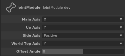
The axis orientation of the joint can be set in the Attribute Editor.
Main Axis: The axis that points in the direction the joint points at
Up Axis: The axis that will align with the World Top Axis
Side Axis: Whether the last axis is the positive of negative normal to the plane formed by Main Axis and Up Axis
World Top Axis: The world’s axis to use as top axis
Offset Angle: Rotate the Up Axis arount the Main Axis
aim
The joint points at the rest_position connected to its aim plug.
parent
To parent a joint, connect a world_transform to the parent_world_transform of the JointModule-dev.
FK Chain
FK chains are JointModule-dev connected to each other with the last joint being an EndJointModule-dev.
Simple chain
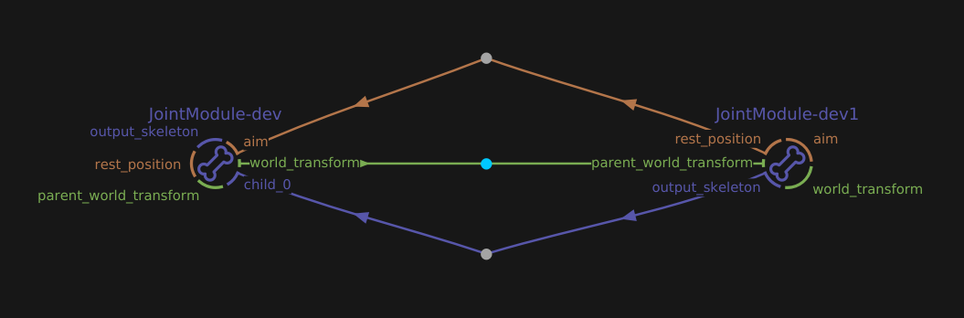
Connect two JointModule-dev:
Connect the second joint’s rest_position plug to the first joint’s aim
Connect the first joint’s world_position to the second joint’s parent_world_position
Right-click on the first joint, select Resize Children Slots and enter 1
Connect the second joint’s output_skeleton to the first joint’s newly created child_0 plug
The end of a chain is an EndJointModule-dev node instead of a JointModule-dev. Connect it as if it was a JointModule-dev.
Note
An EndJointModule-dev is a JointModule-dev without a controller.
See also
The simple_joint_chain.rumba sample.
Y chain
A Y chain happens when a joint has two children instead of just one.
Connect a second child to a JointModule-dev:
Connect the parent joint’s world_position to the second child joint’s parent_world_position
Right-click on the first joint, select Resize Children Slots and enter 2
Connect the second child joint’s output_skeleton to the parent joint’s newly created child_1 plug
With this configuration, the parent joint is aimed at the first child.
Note
In the sample, a third child was created (an EndJointModule-dev) to handle the aim of the parent joint.
See also
The y_joint_chain.rumba sample.
IK
Rumba Rig provides an IK solver for 2 segment skeletons (e.g. arms and legs), the IKSolverLimb2 Node, used in the ArmModule-dev Node. The IKSolverLimb2 Node allows to define the angle for the middle joint using either a solid angle or a pole vector. It also manages stretch and reverse stretch features.
Curve Skeleton Element
MatrixCurve
A MatrixCurve is a curve defined from control matrices that evaluates a transform matrix.
- The shape of the curve is defined w.r.t. the curve type:
ConstrainedBezier: the curve is a piecewise cubic Bezier, whose tangents are defined w.r.t. the control matrices.
Bezier: the curve is a piecewise cubic Bezier, whose tangents are automatically computed from the control positions.
Spline: the curve is a cubic Nurbs defined from the control positions.

- The evaluated transform matrix components are evaluated as follows:
the translation is defined on the curve.
the scale and shear are defined by piecewise cubic interpolation from the control matrices’.
the rotation is computed w.r.t. the orientation mode:
Free: the rotation is defined from the cubic interpolation of the control matrices’.
Constrained: the rotation is defined as for the Free mode, but made tangent to the curve along the MatrixCurve’s main axis.

CurveModule
The CurveModule-dev Node creates a skeleton element that consists in a MatrixCurve, built using the MakeMatrixCurve Node.
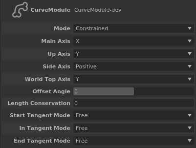
In the Attribute Editor, the orientation parameters are the same as the ones from the JointModule-dev. The others are:
Mode: If constrained, the Main Axis of the joints will always be aimed at the next joint, else it will keep its original direction.
Length Conservation: 1 if the length of the curve doesn’t change, 0 if it can.
Start/In/End Tangent Mode: If free, the tangent of the control point will point to the next control point, else, the tangent keeps its original direction.
Note
By default, a CurveModule-dev Node has five control matrices which define the MatrixCurve. To change the number of controllers, right-click on the Node and select Set Controls Number. This cannot be done on a referenced CurveModule-dev node.
See also
The curve_spline.rumba sample.
Skinning Curves
When a MatrixCurve is used as a skeleton element for skinning, two “fake” joints are inserted in place, both holding the MatrixCurve as their geometry and the first one holding the curve element parameters:
the curve in rest pose
the curve length in rest pose
the curve length conservation animation channel value
Regarding the skinning weights, these come in two parts:
the curve attach of the vertices telling the curve parameter to use when looking for the transform to apply to each vertex
the actual skinning weight for the curve
When applying the Skinner deformer, each vertex will then be skinned w.r.t. a different matrix evaluated along the curve.
Constraints
There are two types of constraints: the transform constraint and the aim constraint. Both can take multiple targets.
Transform Constraint
The Constraint node handles the transform constraints. It can be set to contrain the translation, rotation, shear and/or scale of a node and is weighted.
Simple contraint of a Cube by a Cross:
Create a Cube, a Cross and a Constraint node
Connect the Cross’s world_transform to the Constraint’s target_0 plug
Connect the Constraint’s output to the Cube’s parent_matrix
Add a target to a constraint:
Create a Sphere node
Right-click on the Constraint node and select Resize
Set the number of targets to 2
Connect the Sphere’s world_transform to the Constraint’s newly created target_1 plug
Select the Constraint and, in the Attribute Editor, change to Weight 1 value to 1
Aim Constraint
The AimConstraint node handles the aim constraints. It works as the Constraint node.
Simple aim constraint of a Cube that aims at a Cross:
Create a Cube, a Cross and an AimConstraint node
Connect the Cross’s world_transform to the AimConstraint’s target_0 plug
Connect the AimConstraint’s output to the Cube’s parent_matrix
Follow
There are two type of nodes that can have a follow option, the JointFollowModule-dev and the ControllerFollow.
Joint Follow
The FollowJointModule-dev is a like the JointModule-dev but offers the ability to select which object it follows. The first object that it follows is its parent, then it can take any number of followable objects. It also has an aim option.
The controller of a FollowJointModule-dev has a Compensation Mode and a Follow channel. The first one switches between Aim and Follow, the second is the list of available follow objects.
Follow a Cube:
Create a FollowJointModule-dev, a JointModule-dev and a Cube
Create a chain between the JointModule-dev (parent) and the FollowJointModule-dev (child)
Right-click the FollowJointModule-dev, select Resize Follow Slots and enter 2
Connect the cube’s world_transform to the FollowJointModule-dev’s follow1 plug
Enter the FollowJointModule-dev node
Right-click on c_FollowJointModule and select Plugs > follow > Edit Desciption
In the Edit Description window, enter :
{ "enum":{ "Parent":0 , "Cube":1 } }then click Set Description. This adds the Cube entry to the Follow switch.
Aim at a Cross:
Create a FollowJointModule-dev and a Cross
Connect the Cross’s world_parent to the FollowJointModule-dev’s target
See also
The follow_joint_module.rumba sample.